

I admit it – I have a problem. I am an OBDII addict. I love to learn more about the ‘electronic technology’ that is inside my 2005 Aston Martin DB9 (or really any Gaydon era Vantage, DBS, Rapide, Virage or Vanquish). I started my OBDII habit with my Autel MD802, then moved on to the Foxwell NT510, and then a ThinkDiag. All those were gateway drugs until after a 2+ year search I was able to source an actual Aston Martin Dealer System (AMDS) computer, VCI module and cable. Nirvana achieved.
One unique part to that system is the Vehicle Communication Interface (VCI) cable. It is a bespoke Y-cable, one end links to the VCI module, and the other has two ends that connect to the two OBDII ports that are in the Gaydon era cars like mine (the Powertrain and Body connectors). Wanting to learn more about what makes this cable special, I took mine apart to see how its made so that it might help you make one of your own, or repair one that you might already have. There were a few surprises along the way.

Some might think I am nuts taking it apart, and you might be a little right. I had the same thoughts as I was disassembling the covers and peeling back shrink tubing “Why the hell am I doing this?”. Part curiosity and part wanting to demystify what’s in the box so others can follow the same path more easily.
Firstly – it is NOT just a standard OBDII cable that would be used in any other car and simply purchase off Amazon. It shares many common features, but the Y-cable design that allows it to talk to both the Body and Powertrain connections at once makes it unique (as far as I know).
The VCI cable has really four areas of interest:
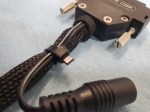
- The connection at the VCI module
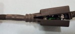
- The ‘Splice’ connector in the middle of the cable where the Y branches out
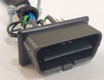
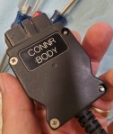
- The ‘Body’ Data Link Connector (DLC) that plugs into the Body OBDII ports on the car.
- The ‘Powertrain’ DLC that plugs into the Powertrain OBDII port on the car.
The overall cable is long. 141 inches long (just short of 12 feet!). That’s 3.54 meters for the rest of the world. I think it’s this long so you can have the AMDS laptop on a cart comfortably outside the car and just have the cable draping in the window. Specifically:
- 99 inches (2.51 m) from the VCI connector to Splice
- 42 inches (1.07 m) from the Splice to each OBDII DLC connector

In general, it was easy to tell the cable is made with very high quality components. It feels like ‘quality’, had rugged connectors, engraved labels, and the actual wire wrapping is a mesh design that is smooth, very flexible and wont scratch the car as it is draped over doors and consoles. The connections inside the connectors are all professionally soldered (unlike my hack jobs at soldering). The wires are stranded copper, and I would guess 18 gauge (sturdy). This is a nice piece of kit.
One might ask if the wires that carry the communication protocols like the High and Low speed Canbus are twisted pair cables (to reduce noise). From what I saw I don’t think so, or if they are the twist is very minimal along the pairs. Ideally they would be twisted.
Can you just buy one somewhere? I wish. [If you have one you’d be willing to sell/donate to me, or know a source on where to buy them – please contact me directly on the Contact page]. My guess is that these are only available to official Aston Martin Dealers and/or only are provided in the entire kit (for a whopping $16,403 USD if you can get one at all). Maybe I am wrong and it might have a an Aston part number that can be ordered. Please let me know if you have any insight here.
Research
As part of my research I tracked down several official sources of data explaining what I should expect at each connector. Essentially the diagrams of what the VCI cables three connectors plug into. I found the pin out table for the VCI itself, and then the official Aston Martin wiring diagrams that list what wires are connected to the OBDII ports in my actual DB9. These were a great start and define what ‘signals’ are flowing on what wires.
- Official VCI module manual
- Official Aston Martin Body OBDII port diagram
- Official Aston Martin Powertrain OBDII port diagram

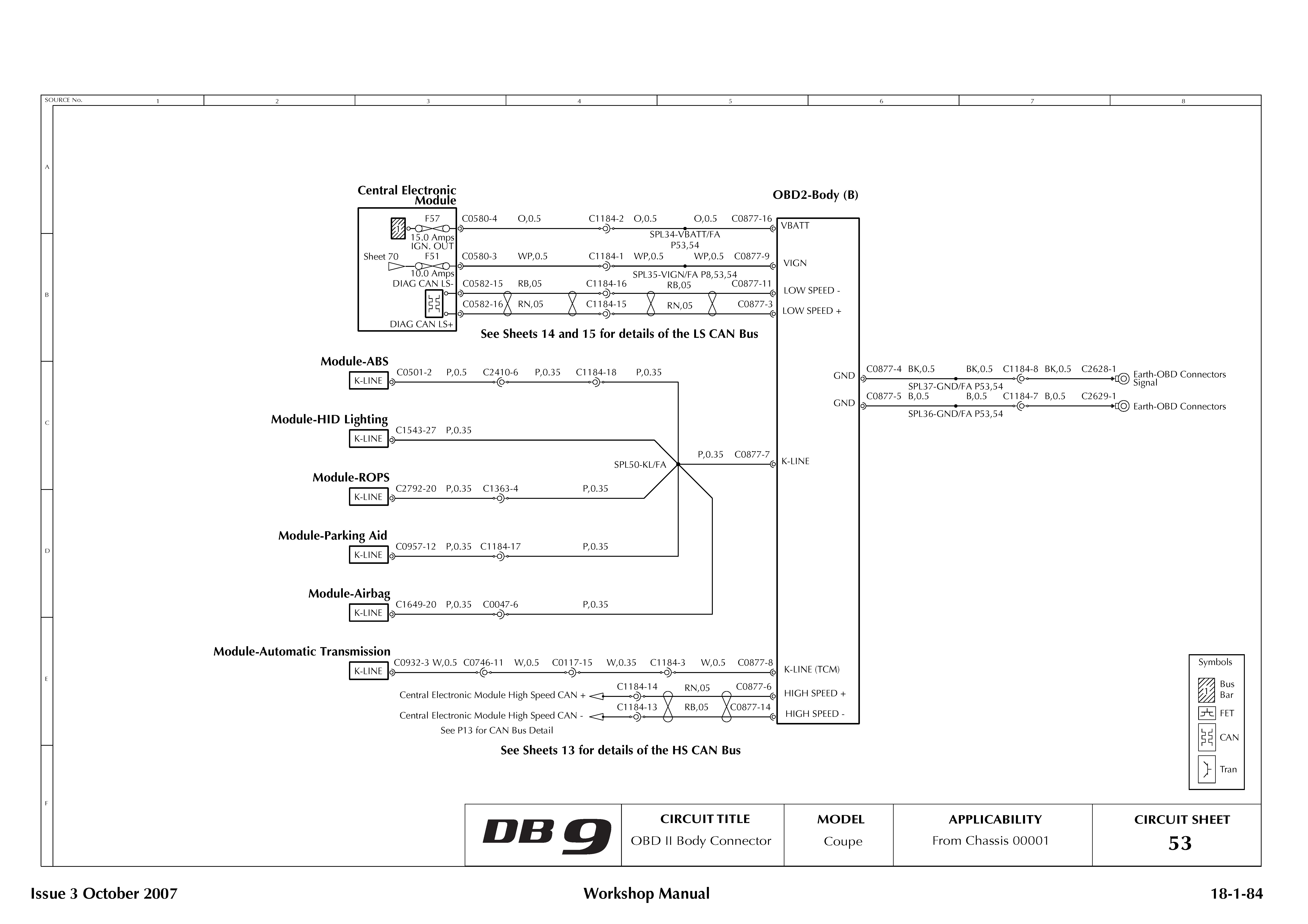

By reviewing those diagrams you can see where 12V power, Ground, High Speed CanBus, Low Speed CanBus and other signals all connect. Now I know what signals are supposed to be flowing between which ports of the VCI Cable.
Teardown
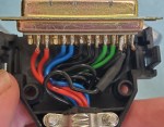
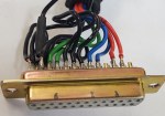
Next it was time to just take it all apart and see what was under the covers. Not a lot of drama here, just a small Philips screwdriver and about 5 minutes work to reveal what was inside each of the connectors. Rather than describing it in words, here are a number of high resolution photos of each of the four connectors.

VCI Connection


Splice Connection


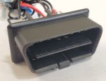
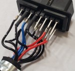
Body Connector


Powertrain Connector


Notable Discoveries
I found a few notable discovers under the connectors. It wasn’t just wires going from point A to point B.
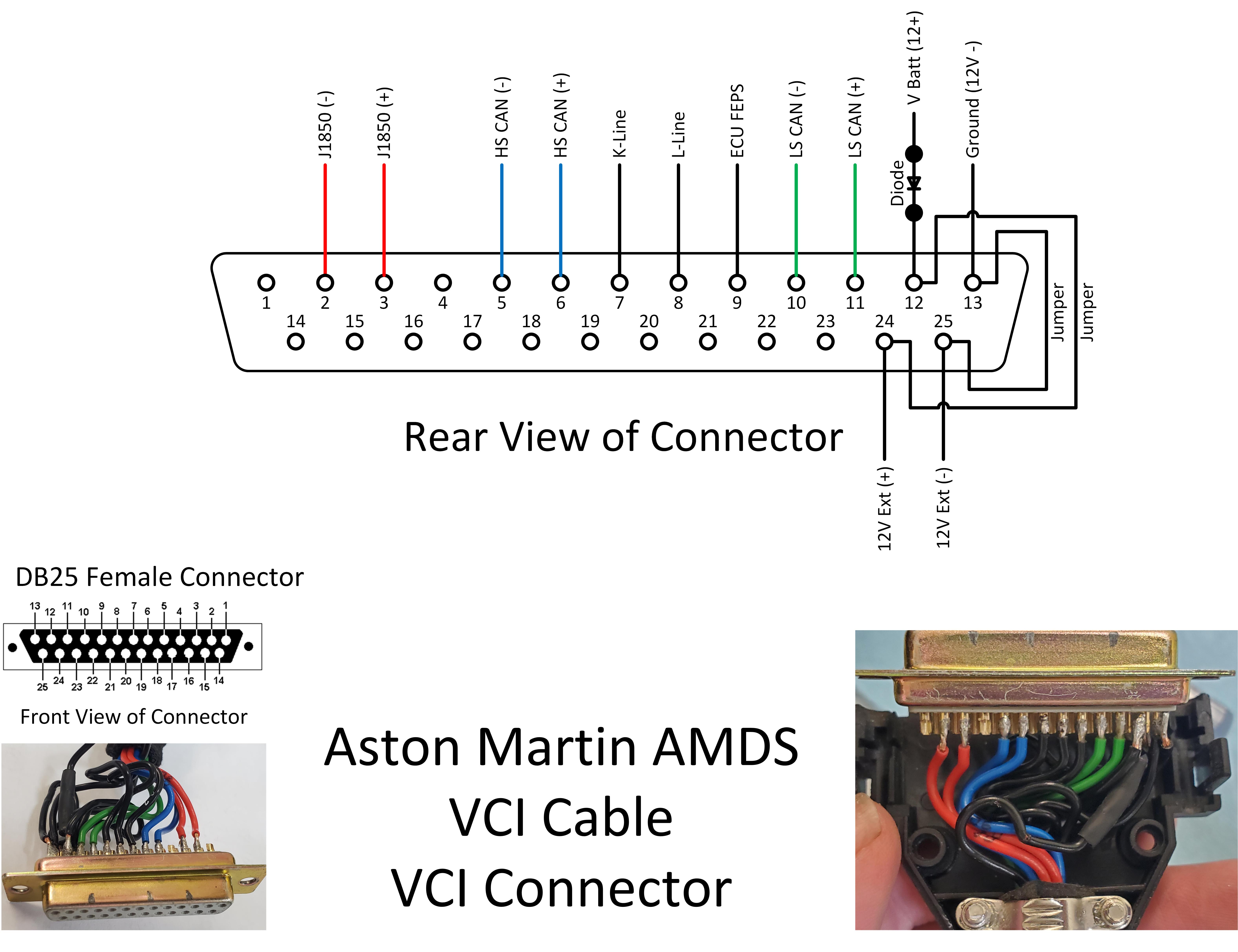
- There was an external 12V power hookup on the VCI connector. I’ve never had to use this with my DB9, but can only imagine it might be needed to work with some older Aston model. Perhaps an earlier DB7 or Gen1 Vanquish.
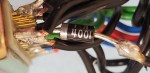
- There was a Diode soldered to the 12V+ pin in the VCI connector. A Diode is a one way flow device for power. It is configured to allow 12V+ power from the car to flow to the VCI connector, but NOT allow 12V+ power to flow the other way (presumably if using the external 12V supply). If you look at my photos (apologies) I think the Diode is a 1 N 4001.
- There are two jumper wires in the VCI connector
- From pins 12 to 24 carrying 12V+ power. Note that the external 12V+ power splices into this as well. I think this jumper is there to support whatever the purpose of the 12V external power was.
- From pins 13 to 25 carrying 12V- ground. Note that the external 12V- ground splices into this as well.
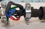
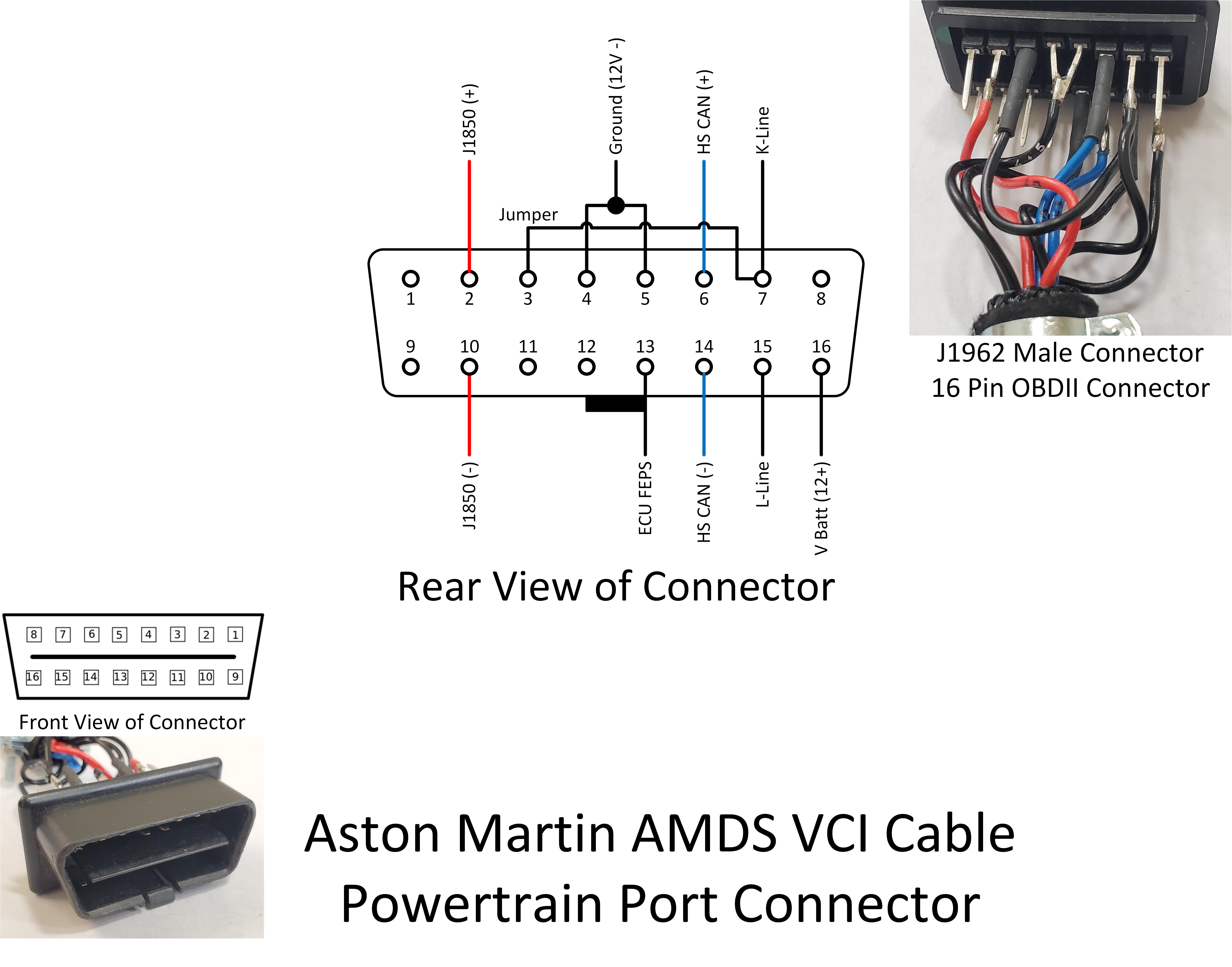
- There is a jumper in the Powertrain Connector
- The K-Line signal on Pin 7 is jumpered to Pin 3. This is likely for an earlier car perhaps as reviewing the DB9 wiring diagrams above doesn’t show anything on Pin 3 of the OBDII connector.
- Most of the ‘splices’ in the splice connector don’t actually appear inside the connector body. The only splice inside the connector were the two Blue High Speed CanBus wires. Five (5) black wires enter the cable at the VCI Connector end, and Nine (9) black wires emerge at the Splice connector. I can ‘feel’ the four (4) splices are buried in-line just as they near the splice connector, and are under a section of shrink tubing that is protecting the cable. This inline splice makes the cable more streamline/slim.
Wiring Schematic
With the covers off and research done, I set about using my Fluke multimeter to verify the pin to pin connections and make an actual wiring diagram that clearly describes the connections and splices. Remember the Aston VCI Y-Cable is not an industry standard. It follows most of the conventions, but has its own twists [pun intended].

At this point its important to understand the pin numbers of each connector. The two OBDII connectors are a J1962 Male with 16 pins total. Pins 1-8 across what I am going to call the top row, and 9-16 across the bottom row. You have to keep track if you are looking at the front or back of a connector, and if you are looking at the Male or Female version of the connector. But, basically pin 16 is the same all the way from the back of the male connector to where it plugs into pin 16 on the female (socket) connector.

Similarly for the DB25 connector that connects to the VCI Module with pins 1-13 across what I will call the top row.
With the pin numbers known, I went ahead and mapped out the wiring schematic that follows. Take a deep breath. The colors match the wires in the cable, and the pin numbers on each connector are called out, and the signal that they carry is labelled as well. If you are going to build one, this is the guide you seek.
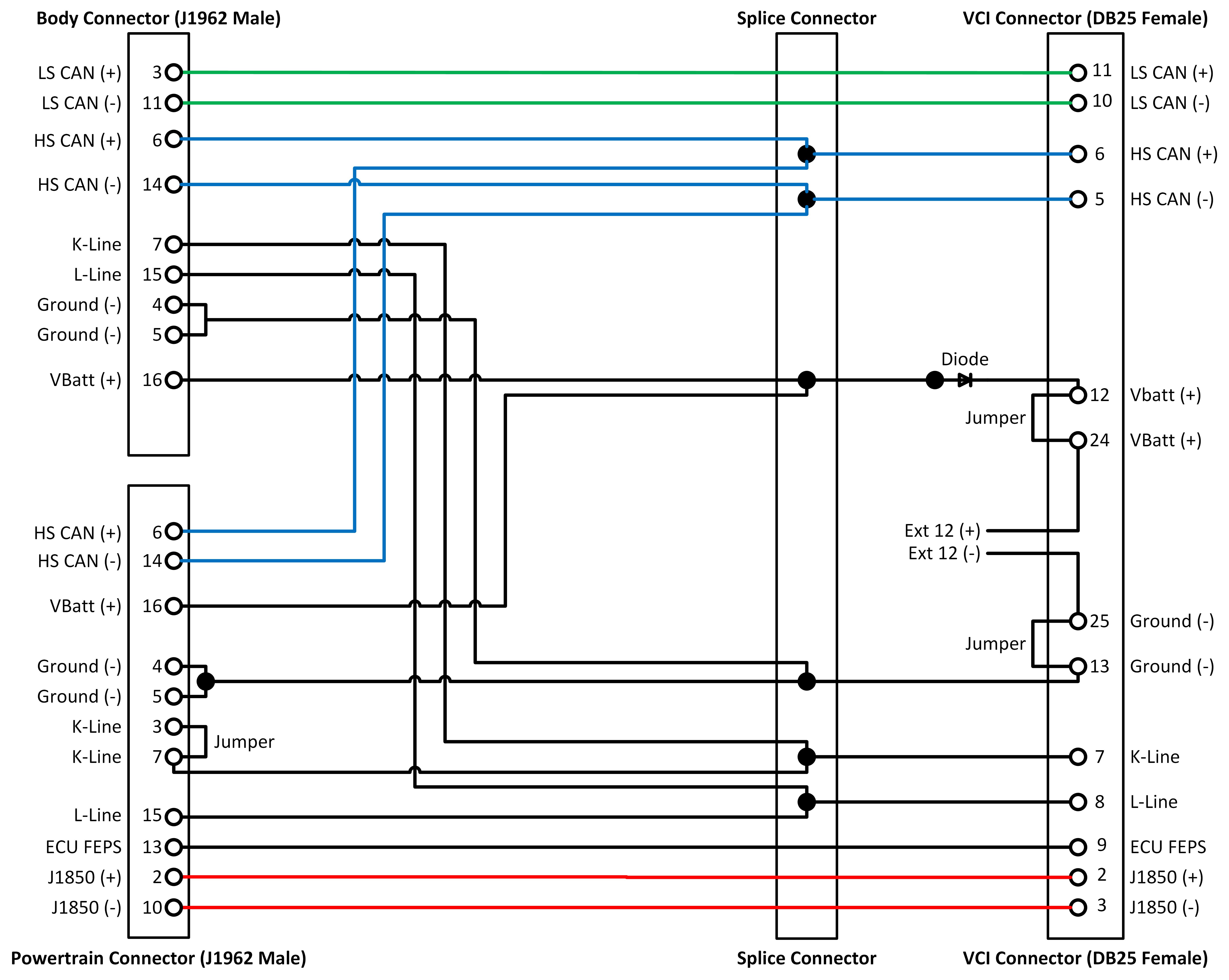
Connector Schematics
Translating the wiring schematic into the physical world, here is what each of the connectors wires up like. Note whether you are looking at the front or rear of each connector. You can click on any of the images to make them larger to view or print.
VCI Connector
Body Connector

Powertrain Connector
The only connector I haven’t built a schematic for is the splice connector in the middle run of the cable. What can I say – it’s where you splice the single line wires into double line wires. They should be soldered and then heat shrink tubing protected. I’m not sure what official type of enclosure to use for this, but maybe I’ll be able to find the source for the official Aston one.
If I was going to build a cable (and I am), what would I do?
There is enough knowledge here now for you to completely build yourself a cable. You need a few parts (the connectors and some wire) and some basic soldering skills. As you can imagine I’m going to try and build myself a cable. I will link [eventually] the parts I source here so that you can give it a try yourself if you want.
- J1962 Male OBDII Connectors
- DB25F Connector
- Splice Connector
- Quality Wire
- Diode and Ext 12V power connector (optional)
- Heat Shrink Tubing
- Wire wrap
Now here is where you might save a bit of time and complexity. As mentioned above the Gaydon cars don’t use all the wires in the full schematic. My theory is that some of those protocols are there to support communication with older model vehicles (like the DB7 and/or Gen1 Vanquish). I’ve made a more minimal schematic of what you’d need to use an AMDS VCI strictly with a Gaydon era car (namely my DB9). Gone are the:
- Red J1850 lines
- L-line
- Diode
- External 12V supply
- K-line to the Powertrain port.
I’ve not double checked the wiring schematics for all Gaydon era cars, but I suspect it will hold true (you can double check it by reviewing the OBDII port wiring diagrams in your models workshop manual). Here is that minimal wiring schematic for a Gaydon only car.

Good luck with your project. Leave me a comment below, or use the Contact page to let me know how it went.
Video
I made a short video about this undertaking, if you can’t sleep one night feel free to check it out:
Bonus Content – About the Protocols
If you’ve looked closely at the wiring diagrams and schematics already you’ve noticed that they are carrying different communication protocols to each connector. There is a reason for this, and I figured I’d write out some of what I learned that is interesting.
High Speed Canbus
The high speed Canbus (not cannibis!) is the pair of blue wires that connects to both body and powertrain connectors. The HS CAN is how the critical Powertrain components communicate (Engine ECUs, Transmission and the Brake system). As you’d expect, the HS CAN passes more information faster than the LS CAN. For an OBDII tool or AMDS laptop to talk to those modules, it will be talking over the HS CAN.
Low Speed Canbus
The Low Speed Canbus (LS CAN) is the pair of Green wires that connects ONLY to the Body connector. The LS CAN is for less critical modules like the Drivers Information Module (DIM a.k.a Dashboard) display, Climate Control, Multimedia, Seat modules, and the convertible roof module in the Volante. The LS CAN passes information on the network slower than the HS CAN, but this isn’t a big deal since the information in these modules is less time sensitive. The “unlock the door” command might take a few milliseconds longer to get transmitted, no big deal.
K-Line & L-Line
The K-line is a xxxx protocol used by xxxx. It is another type of communication network, this one is even slower than LS CAN and is a hub and spoke design. The AMDS and OBDII tools use the K-line to communicate to the xxxx modules.
The L-Line is part of this protocol but appears not to be used by the Gaydon era cars and may be to support older models.
ECU FEPS
I’ve learned that this is a special line between the VCI and the Powertrain connector used exclusively to enable firmware programming/flashing of the Ford ECU’s. Did you know that the Gaydon era cars used Ford ECUs? Apparently this signal needs to be present to put the module into programming mode.
J1850
This is a communication protocol mostly used by Ford. From what I can tell it is not used in the Gaydon era cars (DB9, Vantage, DBS, Rapide, Virage, Vanquish) and may be part of the AMDS and VCI system to support older models.

Hi Steve, What I am interested in is the battery conditioner link lead. Also the trunk/boot fuse box feed terminal rubber isolator/cover if they are available. Let me know.Thanks,Ralph
Sent from Yahoo Mail for iPhone
LikeLike
I was really looking forward to reading about this and maybe being able to help or comment as a CAN expert. But the linky no worky.
If the 2 buses have the same baudrate, it’s simply a matter of connecting them together. Alternatively, it could just be that the CAN adapter is a 2 port affair. No doubt it’s just a rebadged Kvaser or something like that anyway.
If there’s anything CAN based that you’d like to ask me, please feel free. Cheers, Nick
LikeLike
Dear Steve,
When I copy you link the following message is displayed;
It looks like nothing was found at this location. Maybe try a search?
Please can you check this Many thanks,
Jack van Putten
LikeLike
Steve,
Excellent as usual. A related question; after unbolting my seat for work on the park brake microswitch the airbag sensor sent the fault to the ECU. Can I clear this by disconnecting the battery for a couple hours to reboot the system or do I need the OBD scanner to clear the fault?
Digby
LikeLike
Hi, Steve.
An absolute life saving post at the right time. I was, for different reasons, in need of an AMDS cable. Said and done, made the cable ( Minimal Version). Some work to be done but not rocket science following your layout.
Connected it to the car (Vantage V8 ASM) and had no contact with the transmission. Checked the wiring diagrams, and the ASM transmission communicate via K-line on the Powertrain OBD. Added that to the harness and now it works just great.
So adding K-line on the Powertrain OBD in the Minimal Version might be a good idea, enabling to interact with ASM transmissions.
Keep up the good and inspiring work that you share.
/Tomas
LikeLike
Hi. Fantastic insights as always. Many thanks. I have a 2016 DB9GT and it only has a single OBD port. Do you know how this interfaces to the AM diagnostic kit? Ta. Alun.
LikeLike
Can I send you 2 broken cable sets that we have for you to repair -we will pay whatever you feel is a fair fee
My name is Leslie Chill
Tech Service Manager
Galpin Aston Martin
Van Nuys , CA 91406
USA
Cell phone 626 264 4384
E Mail lchill@galpin.com
LikeLike