
If you’ve been replacing your PCV Valves on your Aston Martin DB9 to cure an oil build up problem in your intake manifolds (check out my other articles on this) it’s likely you’ve had your PCV Valve Vacuum Harness Assembly removed and in this article I will explain how to properly reinstall it.
The task itself is pretty easy, but fairly fiddly to get the hoses routed the right way to where they are going so they don’t interfere with all the other components packed in the same place. If you followed my advice when removing the assembly, you should have taken LOTS of photos deep in the bowels of the space to capture where things go. If not, I will do my best here to share my photos and try and explain it.
Again I need to make apologies in advance that there is no video for this topic. I didn’t know how to do it the first time I did it, so I hacked my way through to my current state of enlightenment. Now you get the benefits of that experience, but I just couldn’t make myself stop and take it all apart again to shoot the video, and even if I did I don’t think there is a camera angle that would have shown it well. I hope the following article and photos do the trick.
[Updated October 2017 – a follower of this Blog Mike Potts was kind enough to record video of him following these procedures and he shared his footage with me. Thanks you Mike! You can see the video down below.]
Note: Most of this topic is about where the hoses go. Really pay close attention looking at the photos, and note where a hose is related to the other things in the picture. Does the hose cross over or under that electrical harness? To the left or right of that fuel rail fitting? In front or behind that other vacuum hose. Getting this right is what this step is all about.
Tools Required
 Not many since all you are going it installing a hose clamp and a zip tie:
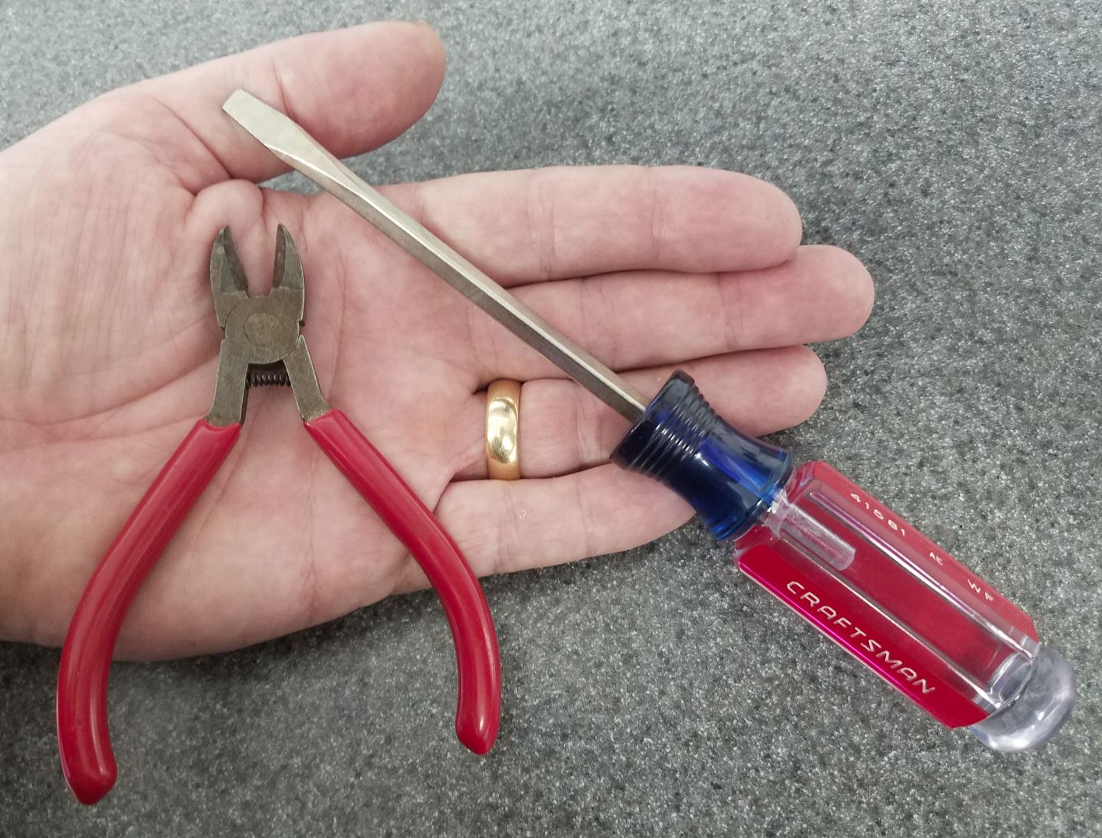
- Flat blade screwdriver or nut driver to tighten a hose clamp
- Side cutters to clip a zip tie
- Your hands to push on a few hose connections
Part Required
In my full article on the part required to change the PCV valves (check it out here) I mentioned that you will need:
-

PCV Vacuum Harness Assembly Your original refurbished vacuum harness assembly or your new one, which ever option you followed.
- An 8” zip tie to replace the one we cut off removing the harness
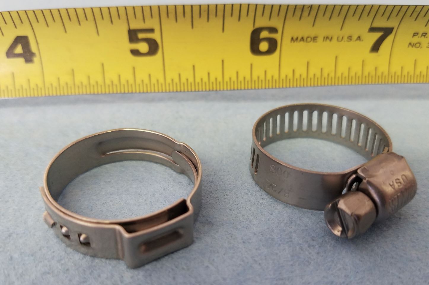
- A 1” diameter hose clamp to replace the one we also cut off

The hose clamp can be either an original Oetiker style (if you have the special pliers, the space to use them and inclination to install it), or do like I did and I purchased a common hose clamp you can tighten with a screw driver (of course, it can come loose easier too).
Procedure
I’ve glossed over the fact so far that there is a ton of work to get into the area where the PCV valves are kept. I was doing this at the same time as changing my coil packs and spark plugs. If you are just servicing your PCV valves you’ll still need to do ALL of the following procedures before getting to the PCV valves:
- Purchase your parts
- Access the Cabin Fusebox
- Depressurize the fuel system
- Disconnect the battery
- Install Fender covers
- Remove the engine bay cross braces
- Remove the intake manifold center brace
- Disconnect the fuel rails and remove the fuel injectors
- Disconnect the ancillaries connected to the Intake Manifolds
- Remove the Intake Manifolds (including the dreaded rear bolts)
- Remove the PCV Valve Vacuum Harness Assembly
- Replace the PCV Valves in the Vacuum Harness Assembly
With all the preliminaries out of the way, we can get on with installing the harness. This might take 10 to 20 minutes to complete depending on your level of patience.
- Your two fuel rails should still be loose and floppy in the center of the engine, and I positioned them both off to the right side (of the car when sitting in the drivers seat).

- Wrestle the whole octopus back loosely into the V of the engine to start with.
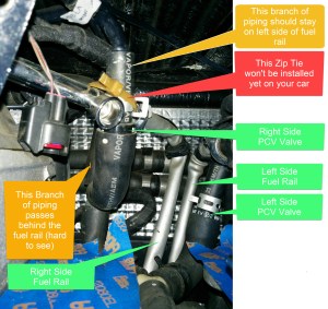
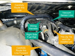
- Slip the right rearmost larger diameter horizontal black hose under the right side fuel rail so it passes roughly above and behind the right side valve cover.
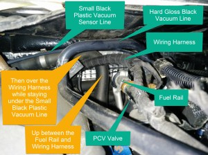
- The right side PCV valve should still be upright and be on the left side of the right side fuel rail (remember, left as if sitting in the driver seat, opposite of how it looks in the photo). Take note of the photos here, this is the trickiest part, and really hard for me to describe in words.
- This right side horizontal hose needs to weave across behind the valve cover and come out at the stainless steel ‘Y’ connection on the right side of the engine bay where we cut off the hose clamp before.
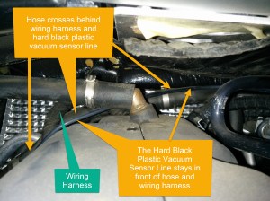
- Pay close attention to the separate small black plastic vacuum sensor line that runs right beside it that ultimately connects to the back of the intake manifold (when it gets reinstalled). It can easily get ‘lost’ in the back while you are wriggling the larger hose around. Check out my photos, you can see the small black plastic line crosses over just above our hose, and is free and clear at the spot where it will eventually connect to the intake manifold.
- No need to connect the hose yet, we want to get the other portions positioned first.
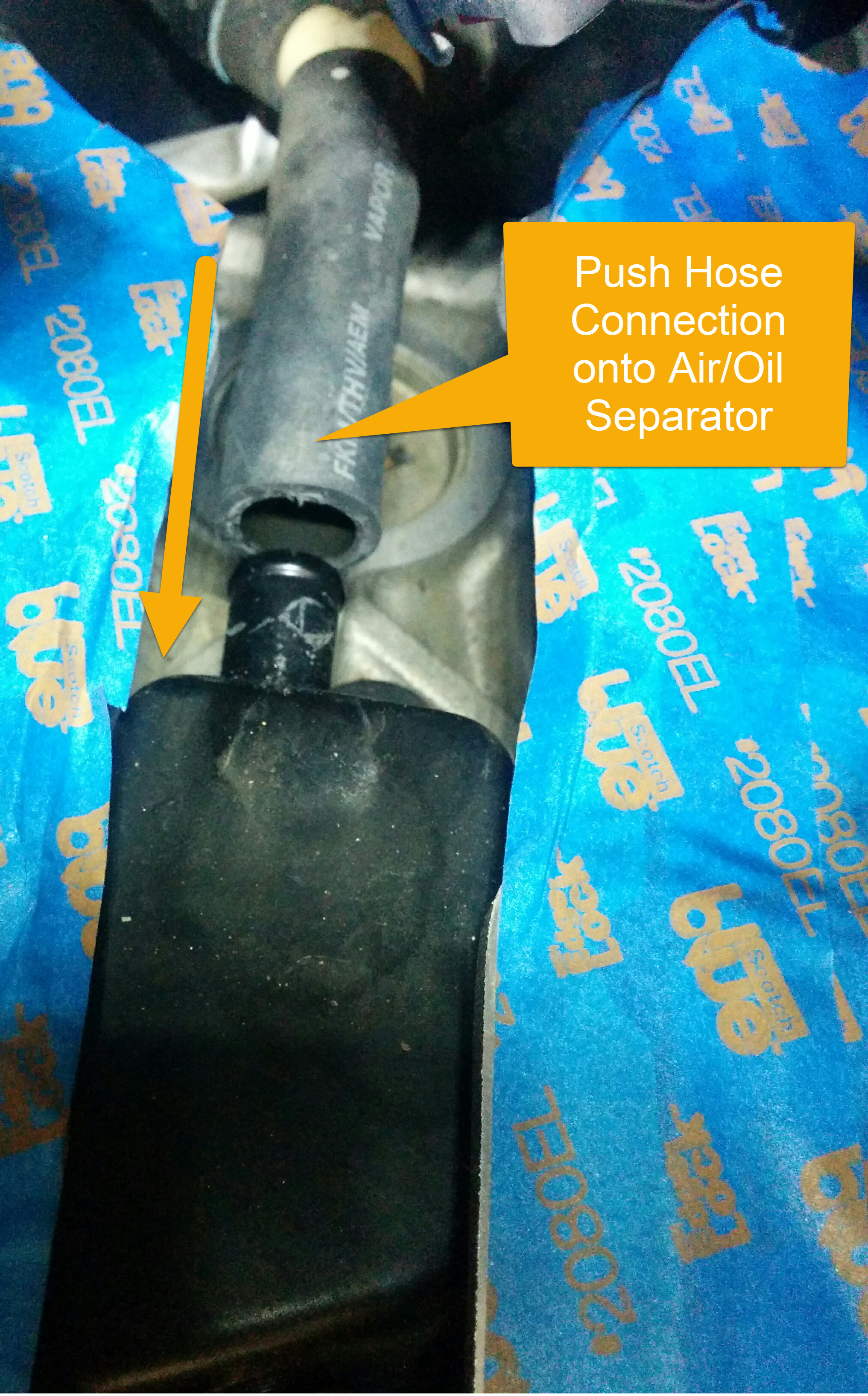
- Now we want to connect the bottom of the harness back to the rear most air/oil separator. This is just a simple push fit connection, and reach in with your hand and push/pull it firmly all the way onto the canister.

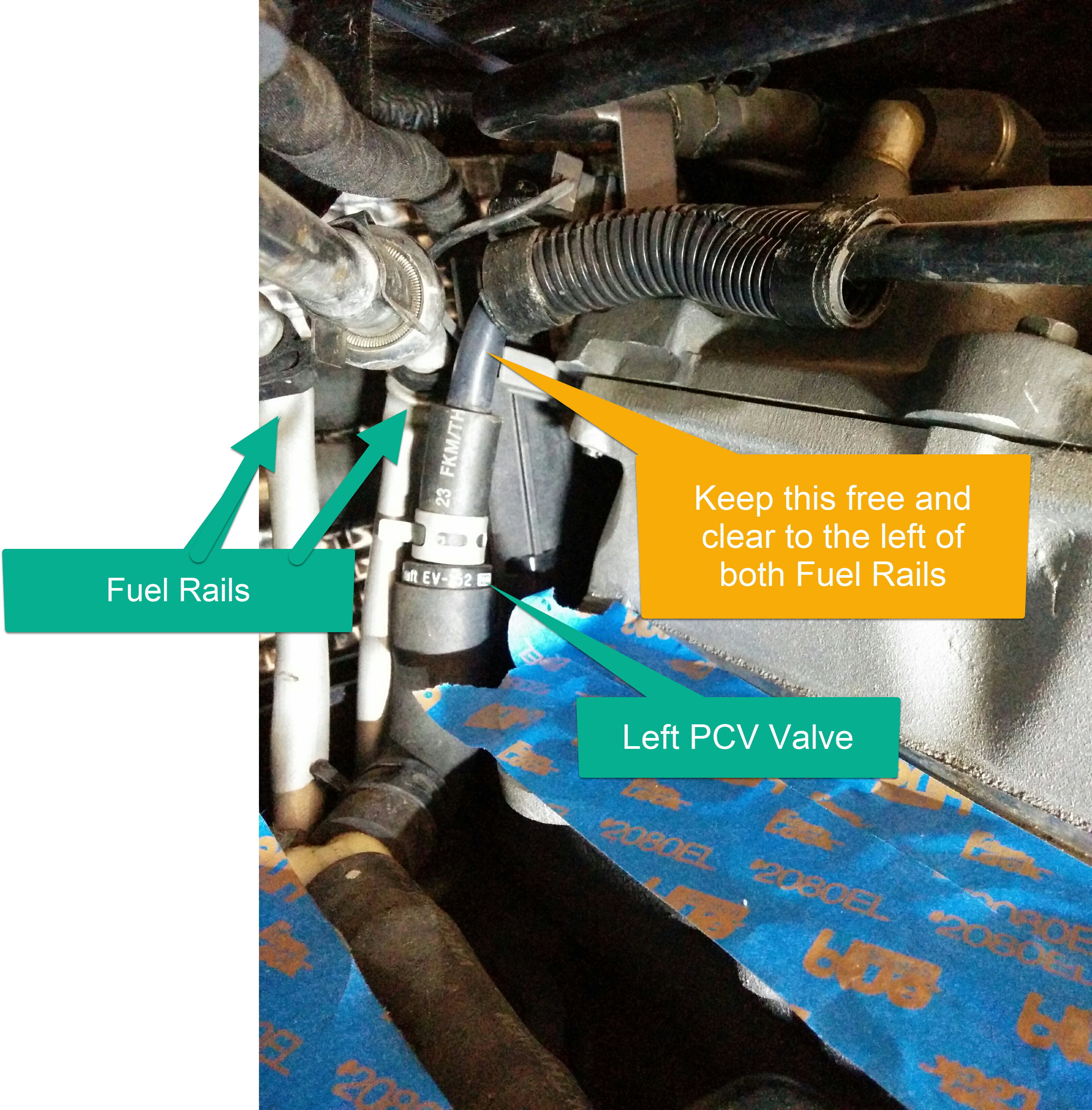
- Next you want to check the rough positioning of the left side PCV Valve. It also should be upright, and sitting just to the left (left when sitting in the car) of the left side fuel rail.
- Nothing to attach, just be sure its free and clear, and the hard black plastic vacuum line is loose and floppy running forward.
- Check out this photo on the proper positioning, noting that both fuel rails are sitting off to the right side of the car.

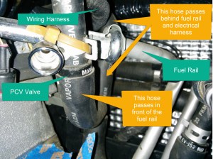
- Now we can focus on the right side PCV valve and black plastic line that runs forward. This has to weave around some stuff. Up over the right side fuel rail, electrical harness and vacuum sensor line. See the photo.
- Make sure the hard black plastic vacuum line is loose and floppy running forward.
- Make sure the hard black plastic vacuum line is loose and floppy running forward.
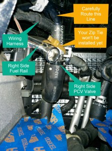
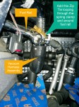
- With all the hoses roughly in place, now we can fix the right side hose with the zip tie back to the right side fuel rail.
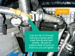
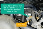
- The photos will need to tell the story here, but pay close attention to the fact that the factory weaves the zip tie THROUGH the slot in the upper PCV Valve hose connection spring clamp, and then wraps it around the fuel rail immediately behind the rearmost fuel rail cup.
- Be careful NOT to accidentally trap any other lines in the zip tie like the wiring harnesses or small vacuum sensor line. Lots of crap tucked back in this area, so take your time and keep referring to the photos until it looks just right.
- Just barely snug this line up, don’t cinch it super tight. If you do, later in its life when the plastic is well baked and more brittle the stress might cause it to snap. Just a light snug to keep all the bits sucked up together if all that is needed.
- Trim the zip tie using your side cutters
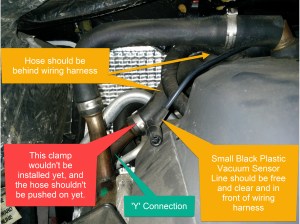
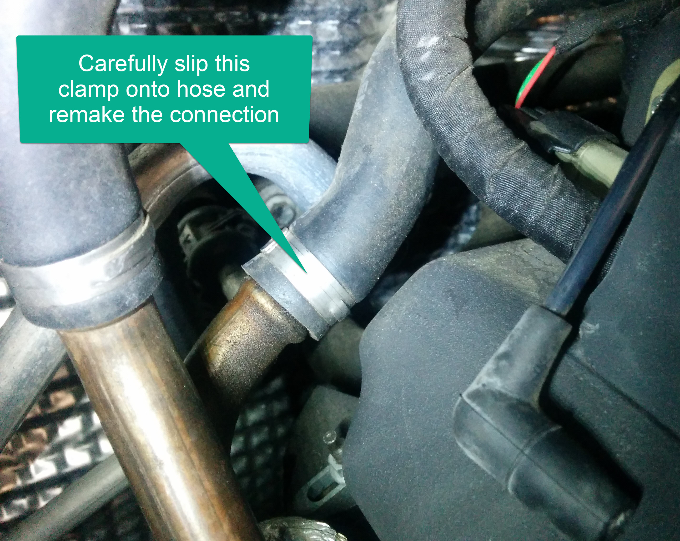
- Slip your 1” diameter hose clamp over the black horizontal vacuum hose we previously positioned near the stainless steel ‘Y’ connection on the right side.
- Push the hose onto the ‘Y’ connection being careful not to let the loose hose clamp drop off into the unreachable abyss behind the engine block.
- When placing the clamp, think about where the head needs to be to access it with your screwdriver to tighten it, or crimp it with the Oetiker pliers.
- Snug up the hose clamp.
- Doesn’t need to be massively tight since this is a vacuum line, but snug enough to not rattle loose.

- Doesn’t need to be massively tight since this is a vacuum line, but snug enough to not rattle loose.

That should be it. You can move your fuel rails and hard black plastic vacuum lines back into the center of the space again and make sure everything is free and clear ready for the next steps.
Next Steps
You have a bunch of work to finish up still including:
- Prepare and Install the Intake Manifolds (including gaskets)
- Prepare and Install the Fuel Injectors and Connect the Fuel Rails
- Reconnect the ancillaries to the Intake Manifolds
- Prepare and Install the Intake Manifold Center Brace
- Prepare and Install the Engine Bay Cross Braces
- Reconnect the Battery
And because you had the battery disconnected you will need to:
- Recalibrate the Door Window Glass Auto Drop Positioning
- Calibrate the Seat Modules
- Set the Clock
- Relearn the Misfire Correction Factors. This is the final and important step necessary since the old calibration would be lost with the battery disconnect.
Video
Here is a video of the process with footage supplied by Mike Potts.

Great write up and video guys. Thank you Mike for the video, great to see a fan of Aston 1936 participating to this level.
LikeLike